Overview
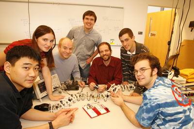
The Olin Snake Project was started by Matt Aasted, Gui Cavalcanti, Chris Dellin, Elizabeth Kneen, and Jon Tse due to an interest in snake robotics, sparked by Professor Gill Pratt, and a desire to go above and beyond the requirements of Olin College’s sophomore-year Principles of Engineering (PoE) class, taught by Professor Brad Minch.
The content from this page was adapted from here. It was prepared by the Snake Team as a whole.
Principles of Engineering
Sophmores enrolled in PoE are expected to "work in small multidisciplinary teams to design and to build a mechatronic system of their own choosing," reads the description on the PoE website.
PoE provides roughly $300 to each team for material costs and expects students to work 8 hours a week outside of class. However, the nature of our project required additional funding and time, so as a group, we added more credit-hours in the form of independent research at Olin. The Olin Self Study, Independent Study, and Undergraduate Research Board (OSSISURB) provides more funding on a per-group basis, the amount of which subject to need and of course, budget. From OSSISURB and Professor Pratt we received an additional $2000, bringing our total funding to $2300. (This figure includes purchasing of raw materials for next semester.)
Process
Coming into the project phase of PoE, our group had an advantage over our classmates since we began work towards the beginning of the semester, doing preliminary research and component trade studies in addition to the assigned classwork. By mid-semester, when the class had completed the in-class introductory labs, we had completed our trade studies and had our Phase One snake fabricated and undergoing testing.
During our initial research we came across a multitude of modular snake designs, where each segment of the snake would be jointed to the next at a fixed location. Rather than repeat the direct-drive solution, we came up with a few unique ideas of our own, and eventually settled on the linkage design presented on this webpage. The design emphasizes the continuous nature of a snake by using an actual spine, in this case, flexible Lexan rod, and using servos and linkage arms to control the curvature of the spine.
By controlling curvature instead of joint angle, we feel we have approximated the actual mechanism at work in a live snake, where muscles attached to the ribs control curvature of the spine. By the end of the fall 2005 semester, we had created 4 generations of planar (2D) snake designs. Our final deliverable for our Principles of Engineering class was a 4 foot long, tethered (for both power and control), 4th-generation planar snake (Phase Four).
Instruction
Throughout this process, we had weekly status meetings with Professor Pratt, our OSSISURB advisor. Professor Pratt took a very soft approach to the project. Instead of setting hard deadlines and actively directing us towards specific goals, he took a hands off appraoch, answering questions as necessary and gently steering us away from potential pitfalls.
This is not to say that he told us outright not to pursue a course of action, he mainly just smiled and said: "That’s great," and let us find out for ourselves. Professor Bradley Minch, who was the instructor for PoE, also took this approach. As part of the class’s requirements, we wrote and submitted two progress reports, but the role Professor Minch played was mainly that of a resource we could go to for technical help.
This style of instruction allowed us to make our own mistakes and to learn from them, but helped us avoid project-ending failures. If we started going too far down the wrong path they would open our eyes to exactly what we were getting into and give us a soft nudge back into safer territory.
The Next Step
Chris and Gui went on to build a three-dimensionally actuated sidewinding snake with some help from the rest of the team. The next potential step would be to investigate three-dimensional, completely untethered robotic snakes.
Electrical and Computing Components
USB Host
All of the control algorithms are run in C on a laptop computer which serves as the USB host. Commands are sent to a PIC microcontroller, which are then transmitted over I2C to the servo-controller.
Embedded Computing Components
PIC18F2455
The PIC enumerates itself as a USB to the USB host computer. The PIC provides several vendor-specific requests as a USB device, the most important of which is the I2C write vendor-specific request.
All the I2C write request does is take a servo command sent from the host computer to the servo-controller over the I2C protocol. The other vendor-specific requests are diagnostic in nature, turning on troubleshooting LEDs.
SD-21
The SD-21 is an off the shelf servo-controller capable of controlling 21 different servos using PWM signals. It has a DIPP socket for a PIC to control it, or can be controlled over I2C.
Actuators
The HS-81MG servo from Hitech serves as a transducer between electrical and mechanical systems, translating control logic to physical spine curvature. Please see the individual snake phase descriptions for a more detailed explanation of how we used the servos.
PCB Designs
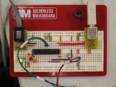
This particular PCB was designed to replace our breadboard. It essentially has a 26-pin DIPP socket for a PIC18F2455 which translates USB traffic to I2C commands to the SD-21 servo controller. It also has a number of USB-controlled (through the PIC) LED status indicators for diagnostics and debugging.
We used ExpressPCB Design to manufacture the PCB.
Next Steps
One next potential step would be to get a gumstix running on the snake itself along with batteries for power, allowing us to control the snake without a tether over 802.11b WiFi.
The gumstix embedded computing platform is essentially a Intel XScale procesor running a linux kernel. Our model, the connectix 400, has a 400MHz XScale processor, Bluetooth connectivity, as well as expansion cards for servo control, general I/O, both digital and analog, and 802.11b connectivity.
Control Algorithms
The snake is controlled on a per servo basis from the host computer. Commands to set servo position and velocity are sent via a USB request to the PIC using libusb, which then translates each request to its corresponding I2C request. The SD-21 Servo Controller then forwards the parameters to the servos themselves.
Simplistic Serpentine Gait
The Phase One and Phase Two snake use a very simplistic serpentine gait algorithm. The simplest form of serpentine motion in a snake a that of a sine wave. Since servos are position-controlled, we update each servo on the snake with a sine wave, changing in time with a phase shift between each servo. The net result is a ripple effect in the snake, much like what you see in a Slinky.

|
Theory
This motion is not a pure serpentine gait, especially since the sine wave we are feeding the snake with exists in the frame of reference of the servo and not the frame of reference of the snake. In fact, a true serpentine gait is not actually a pure sine wave. Since phases One and Two were prototype models, an inaccurate representation for serpentine motion was acceptable, even useful in debugging our mechanical designs. |
Continuous-Spine Serpentine Gait
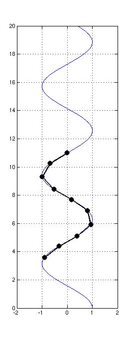
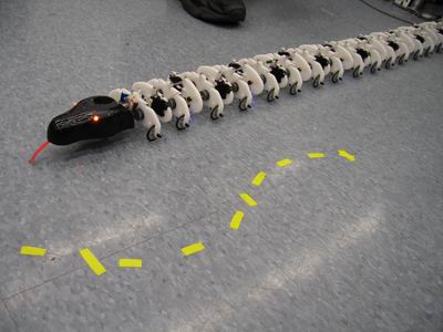
The control algorithm for snake phases Three and Four is best viewed as a type of brute-force algorithm for the computation of joint angles. In software, a path is laid out on the ground in front of the snake, and for each head position along that path, the software computes the joint angles needed to keep each node on the path. In this way, the snake can follow the path on the ground (in "world-space") while each node only moves tangential to the path.
|
|
Theory
It is this reliance on tangential motion that allows the snake to move forward; since each node has very little friction in its direction of motion but a large amount of friction perpendicular to its direction of motion, the entire snake tends to move forward. The physics is not unlike that of sailboat with its keel pointed at some angle to the wind; while the wind force may not be in the direction of motion, the boat is only allowed to move along its keel axis. In the snake system, each servo is controlled so that the only way the entire snake can travel in its low-friction mode (tangential to each link) is by following the path on the ground laid out in software (each node’s "keel" direction). |
Firmware
The firmware for the PIC18F2455 serves as a translator between the USB and I2C protocols. There is a vendor request which essentially puts the data from the USB host into a buffer, then forwards it to the servo-controller over I2C.
At one point, another function of the firmware was to read input from a joystick for controlling the snake. Gameport joysticks use potentiometers, so the easiest way to do this was to read the voltage drop across the joystick using the ADCs in the PIC, then transferring them over USB to the USB host.
case WRITE_I2C
        banksel USB_buffer_data+wValue

        ; I made a design decision here: we read high, low of wValue and low,
        ; high of wIndex. This is because the servo position is little endian
        ; while we want to encode register number/speed

        movf    USB_buffer_data+wValueHigh, W, BANKED
        movwf   Transmit_buf,BANKED
        movf    USB_buffer_data+wValue, W, BANKED
        movwf   Transmit_buf+1,BANKED
        movf    USB_buffer_data+wIndex, W, BANKED
        movwf   Transmit_buf+2,BANKED
        movf    USB_buffer_data+wIndexHigh, W, BANKED
        movwf   Transmit_buf+3,BANKED           ; puts 4 bytes into transmit buffer,
                                                ; taken from wValue and wIndex
        movlw   low Transmit_buf
        movwf   FSR0L, ACCESS
        movlw   high Transmit_buf
        movwf   FSR0H, ACCESS                   ; set up the pointers to read
                                                ; from our array

        bsf     SSPCON2, SEN, ACCESS            ; generate a start condition on
                                                ; the I2C bus
        repeat                                  ; do nothing...
        untilset PIR1, SSPIF, ACCESS            ; ...until I2C operation
                                                ; completes
        bcf     PIR1, SSPIF, ACCESS

        movlw   0xC2
        movwf   SSPBUF, ACCESS                  ; write the address/control byte
                                                ; to the I2C bus
        repeat                                  ; do nothing...
        untilset PIR1, SSPIF, ACCESS            ; ...until I2C operation
                                                ; completes
        bcf             PIR1, SSPIF, ACCESS
        ifset SSPCON2, ACKSTAT, ACCESS          ; if the slave device did not
                                                ; acknowledge...
                bsf     UEP0, EPSTALL, ACCESS   ; ...set EP0 protocol stall bit
                                                ; to signify Request Error
                break
        endi

        movlw   0x04                            ; put 4
        movwf   COUNTER, BANKED                 ; ...into COUNTER
        repeat
                movf    POSTINC0, W             ; this reads from the array and
                                                ; increments the pointer for us;
                                                ; could alternately use PLUSW
                                                ; to access index array;
                                                ; see page 74
                movwf   SSPBUF, ACCESS          ; Address first byte
                repeat                          ; do nothing...
                untilset PIR1, SSPIF, ACCESS    ; ...until I2C operation
                                                ; completes
                bcf     PIR1, SSPIF, ACCESS
                decf    COUNTER, F, BANKED
        until COUNTER, ==, 0

        bsf     SSPCON2, PEN, ACCESS            ; generate a stop condition on
                                                ; the I2C bus
        repeat                                  ; do nothing...
        untilset PIR1, SSPIF, ACCESS            ; ...until I2C operation
                                                ; completes
        bcf     PIR1, SSPIF, ACCESS

        banksel BD0IBC
        clrf    BD0IBC, BANKED                  ; set EP0 byte count to zero
        movlw   0xC8
        movwf   BD0IST, BANKED                  ; send packet as DATA1,
                                                ; set UOWN bit
        break
Phase One Snake: Direct Drive
The Phase One was designed to have an extremely simplistic mechanical design, allowing for very fast manufacture. It consists of 6 overlapping plates, pinned together by the output shafts of the servos. The "head" of the snake is a mounting plate for the SD-21 servo controller.
The point of the simplistic design was to allow the electrical engineers on the team to write code for the servo controller while allowing the mechanical engineers to continue developing new designs for snakes.
Mechanical Design
All of the parts were cut from sheets of 1/8" Delrin by a laser cutter. All of the servos were mounted on the each plate so that their output shafts were exposed on the underside of each plate.
Problems and Solutions
The major issue with the Phase One snake was the stairstep approach in the rib design. The design caused the snake to bend in an arch, with the front and rearmost plates lifting the middlemostplates, preventing them from any significant movement. The snake was therefore able to squirm in the air, but unable to substantially move. Also, the fact that this snake was built in the discrete-segment philosophy made it literally only a prototype for testing and development. The solution, of course, was to continue developing our original continuous spine idea for the snake.
Successes
As our first revision, this design was a triumph for being a snake. It moved, and that was enough.
Electrical/Computational Design
During this phase, we managed to connect all of the components together, getting the PIC mediating between the servo controller and the host computer over USB and I2C.
A sinuosoidal position signal was sent to individual servos, with a phase shift between each servo. This signal resulted in a undulating serpentine motion in the snake, but wiring and mechanical problems made it unlikely that it would have actually movied.
Problems and Solutions
The wires became very tangled because there was no organization. This substantially inhibited the usefulness of this revision. Future snakes would have a spine, so the wiring would run parallel to them, with mounting for it on each rib. Additionally, we burned out two laptop computer system boards because the SD-21 did not turn on and off well on the USB power. To fix this, we added an external 5V power supply to power the PICs, and tied its ground to the laptop computer USB’s ground.
Successes
Along with the mechanical engineering success, we got all of the electrical and computational hardware, software, and firmware integrated in this phase.
Phase Two: First Linkage Design
The Phase Two snake was our first linkage design. It consisted of a 13 "ribs," attached to a Lexan spine in series via clamp collars.
Mechanical Design
Initially, all ribs were assembled using the thermal press; however, after spending 30 minutes per rib for 6 ribs, we decided to use 440 screws in tapped holes to fasten the ribs together. In the end, this cut our assembly time down by a factor of 10. In an effort to conserve raw material, the final revision for this phase used both types of rib.
The servo-bearing ribs (driving ribs) were heat-staked and the non-driven ribs (dead ribs) were fabricated using screws. This prevented us from having to fully re-cut the whole of the snake from Delrin, yet still minimized assembly time.
Problems and Solutions
Our first problem was with assembly time. It was prohibitably difficult to make ribs, so we switched to a different design which helped cut the assembly time down immensely. The real problem with this phase was the sandwich design for the ribs. There were two points of contact on the spine for each rib, making turning the ribs in normal actuation very difficult. We ended up switching to a different clamp rib design in later revisions of the snake.
Initially, we used Lego wheels to support the snake. However, because there were two wheels attached to one long axle without a differential, the snake couldn’t turn effectively, so we ended up scrapping the wheels entirely and just running the snake on its "belly."
Successes
All things told, the continuous spine idea worked very well. The snake managed to move under its own power on the surface of the table. It produced more of a side to side motion than the kind of forward directional movement one would expect from a snake, but it moved successfully.
Electrical/Computational Design
Both electrically and computationally, the Phase Two snake is essentially identical to the Phase One snake.
Problems and Solutions
Because of the length of the snake, we had to fabricate servo-cable extensions out of 22 AWG solid core wire (that was all we had on hand at the time). The added weight and stiffness of of the snake made bending the spine a more difficult job for our servos. Additionally, the placement of the wire was far away from the axis of the spine. Depending on which way the snake was curving, the wire would either have to be longer or shorter, further decreasing the flexibility of the spine. To fix this, we switched to stranded wire for future revisions, and put the wires directly beneath the axis of the spine.
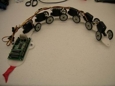
Phase Three: Serpentine Proof of Concept
This was the first snake to achieve a repeatable serpentine gait. It is composed of radically different "dead" (no servo) ribs and "live" (servo-holding) ribs. It was the first snake explicitly designed with wire conduits in mind.
Mechanical Design
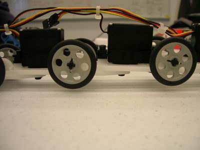
There are two independent wheels and axles on each live rib, which permits individual ribs to turn. Previous snakes attempted to combine two wheels on one axle, which forced wheels to slip as the snake attempted serpentine motion. The ribs were designed with ease of assembly in mind. Snap-together plastic assembly techniques were investigated and successfully implemented, and as a result each rib assembled in less than 2 minutes. With all of these new developments, we could install and remove servos without disassembling the entire snake, which was previously impossible.
Problems and Solutions
The center of mass of the live ribs was on the border of the wheelbase, and as a result the snake was unstable in short sections. Additionally, the snake itself was too light, compounding the problem. In order to weight down the snake, we taped on large sockets from our toolbox. The addition of weight allowed the snake to successfully display a serpentine gait.
Successes
The updated mechanical design, when meshed with the new algorithm performed astoundingly well. The completed snake undulated its way across the robotics lab floor to the end of its tether.
Electrical/Computational Design
The electrical system on the Phase Three snake worked very well. Abandoning 22 AWG solid core for 26 AWG stranded core eliminated the flexibility problem. Additionally, the wires ran along an axis immediately below the spine, reducing the amount of travel for the wires and increasing the flexibility of the snake.
We successfully managed to implement the brute force calculation of servo-space controls from a world-space sinusoid. We also extended our algorithm to allow to the snake to follow a sinusoid projected on any parametrically defined curve, enabling the snake to do things like slither in a gradual curve, or slither along another, larger world-space sine wave.
Successes
This was the first phase in which we were able to successfully implement our continuous spine serpentine gait algorithm. We also were able to steer the snake very coarsely using the superimposed sinusoids.
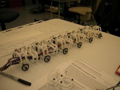
Phase Four: PoE Final Product
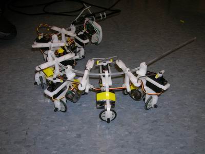
Over four feet long, this snake is the culmination of the first semester’s work on this project. All prior problems associated with past designs have been addressed in this revision to ensure its quality. Like the past two revisions, this snake is actuated by the linkage-servo system mounted to alternating ribs. It has a high degree of precision and control and is substantially more reliable than past designs.
Mechanical Design
Mechanical features of the latest snake include a length of over 4 feet, a thermoformed head, improved linkages, and a sturdy yet flexible design. Prior to designing this snake, the mechanical team set down to address all past design issues:
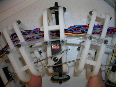
In past designs, the wire linkages would pop out of place during actuation. To address this, we used wire with a smaller diameter, allowing for slippage, and secured both ends of the wire by bending it at ninety degrees to prevent it from easily coming out. Bending the ends an additional 45 degrees allowed for easy insertion. We also attempted to use other linkage designs, made of rounded wire and delrin, but manufacturing time made these designs undesireable.
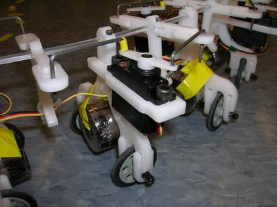
The SD-21’s mounting rib in prior designs had been cantilevered off the snake. In this revision, we added wheels to its rib. Additionally, to minimize wiring problems, we offset it from the rib allowing us to place wire between.
We noted slight plastic deformation in the Lexan spine in other designs. However, after using the INSTRON tensile test machine in the material science laboratory we determined that it was still the best material for its price range.
Problems and Solutions
There were a few problems with the Phase Four snake. We noticed the clamp collars began breaking and plastically deforming in this design revision. This is something to address in the future. Also, a problem with the snap together approach that we kept for this snake design is that the bearing clips (wheel mounts) sometimes snap. This can be solved by changing their tolerances or the material itself.
We also learned a lesson with this revision which was if you are to build 17 like products (the two different groups of ribs), it is wise to set up a jig for consistency and ease of manufacturing. This will be implemented in future designs.
Successes
This was our longest, most complicated snake yet. By incorporating all of our solutions to previous design issues, we got a very good results.
Electrical/Computational Design
In order to reduce the amount of wires, we used 14AWG stranded core cable as a power bus, tapping off 26AWG wires as we needed power. This way, we only had to run one 26AWG wire down the length of the snake for each servo, which made wiring much simpler, and less stiff. We also laser-cut features into the ribs for wire management, making the overall job cleaner and easier to work with.
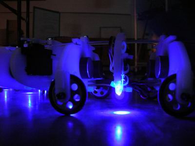
We added Purple LEDs with a 500 Ohm resistor on each powered rib for underlighting and Amber LEDs with a 500 Ohm resistor in the head of the snake as eyes for aesthetics, and we can’t say that it was a bad decision.
Successes
The wiring system was a big success for this snake revision, because each rib was independent of the others, and connected to the main bus for power. This way, we could remove and add ribs very easily. Also, the LEDs were a big hit with both the team and our classmates.