Overview
Project History
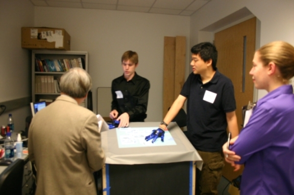
While browsing the web, Professor Mark Chang came across the work of Jeff Han at NYU: http://cs.nyu.edu/~jhan/ftirtouch/. He approached several students, Matt Donahoe, Anthony Roldan, Chris Stone, Jeff DeCew, Olek Lorenc, and Jon Tse, and asked if we wanted to develop a similar touchscreen based on Frustrated Total Internal Reflection (FTIR) technology.
At the time, the idea of applying FTIR to touchscreen interfaces was relatively new, so we investigated its feasibility. We developed some prototypes over the course of the first semester, which were functional, but did not give us the dynamic response we were hoping for. The following semester, Matt and Jeff left the team to develop the K’Nex Computer, and Chris, Anthony, Olek, and Jon continued work on the touchscreen.
In the last phase, Anthony and were are the only two students working on the project. We’ve moved from FTIR to diffuse illumination (DI), as it is easier to implement and is more forgiving.
Multitouch
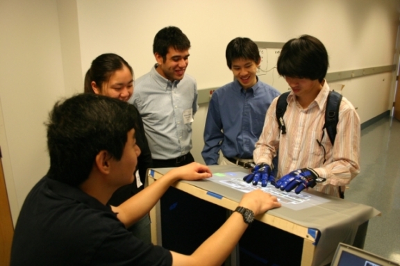
Touch screen interfaces have been around for quite some time, but haven’t really been in general use until recently. Smartphones and tablet PCs are becoming more and more prevalent, and the touch screen interface is growing both in complexity, ease of use, and popularity.
One of the main issues with touch screens is scalability. It’s difficult or prohibitively expensive to build a reliable table-sized touchscreen with traditional sensor technology. Additionally, traditional sensors are grid-based; they determine the cartesian coordinates of each touch. Unfortunately, these systems usually can only read one set of coordinates.
Multitouch interfaces, like Jeff Han’s work and the Apple iPhone, are capable of handling multiple touches. FTIR and DI-based multitouch interfaces are unique in that they are cheaply scaleable.
Multitouch Techniques
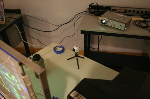
There are two major contenders in the homebrew multitouch arena: FTIR and DI. Both are similar in both function and cost.
The basic idea behind both technologies revolves around an ordinary sheet of plexiglass which serves both as the touch-sensitive and projection surface. A sheet of projector screen is placed flat against the surface of the plexiglass and an image is projected on it from behind by a standard projector. This provides the visual aspect of the touchscreen.
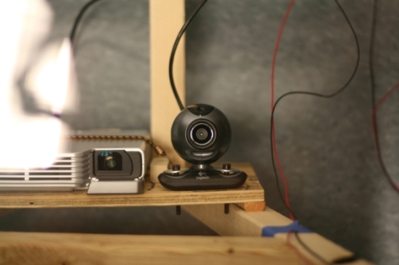
Co-located with the projector is a infrared-only camera which senses the touches on the plexiglass. The method by which the touches register in the infrared spectrum differs between FTIR and DI, but the sensing mechanism is the same. The touches show up as infrared point sources, and the resulting motes of light picked up by the camera are run through a blob-finding algorithm and converted to a set of Cartesian coordinates. These coordinates are the the input to a multitouch-capable program.

|
Webcams and IR

Figure 5. Disassembled Webcam
Webcams are typically created with CMOS imagers, but the higher end ones are created with CCD imaging elements. However, both CMOS and CCD imaging elements are sensitive to IR. Typically, this is undesirable, especially in cell phone cameras and webcams. Manufacturers usually coat the camera lenses with an IR notch filter to block IR light, which we removed with some fine sandpaper. You can see the webcam IR notch filter in the Figure. Note the red sheen. We are interested in getting ONLY IR light though, so we had to get a IR bandpass filter to block the visible spectrum. As it turns out, exposed and developed 35mm camera print film is a decent IR bandpass filter, and attenuates the visible spectrum adequately when layering several pieces of film on top of one another.
|
The benefit of the technology is scalability. Projectors and cameras are already designed to display and capture physically large images, so increasing the size of the touchscreen is as simple as using a bigger piece of plexiglass farther away from the projector/camera pair. As the size of the plexiglass increases, the space available for hands increases, allowing for more touches. However, the size is limited by the practical considerations of large pieces of plexiglass and the maximum resolutions of the projector and camera.
Frustrated Total Internal Reflectance
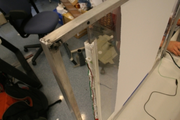
Frustrated Total Internal Reflection (FTIR) is one way of detecting multiple touches. The mechanism is similar to fiber optics. We begin by placing a strong infrared (IR) source along the edges of the plexiglass. This is typically done by arraying IR LEDs.
The IR light is not columated, but some of the light that enters the edge of the plexiglass reflects back and forth between the inside planes of the plexiglass, much like light in a fiber optic cable. This continuous reflection is known as Total Internal Reflection (TIR). Fortunately, the light that does not undergo TIR leaves the plexiglass near the edge.
The plexiglass is now flooded with IR light. By touching the surface with something that conforms to the shape of the glass, such as a human finger, the reflection is disturbed, and the finger appears as an IR "blob," hence the nomenclature Frustrated Total Internal Reflection. As described earlier, the blobs are picked up by the camera behind the plexiglass and processed into Cartesian coordinates.
Diffuse Illumination
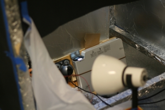
Diffuse Illumination (DI) is another way of detecting multiple touches. The setup is largely the same as FTIR; theoretically, both technologies could be combined to greater effect. The central idea behind DI is to flood the surface of the plexiglass from the projector side with diffuse IR light, illuminating the fingertips of the user. The reason to use diffuse IR light is to ensure a uniform light intensity at all points on the plexiglass.
Objects closer to the surface of the plexiglass will reflect more light, so by very carefully filtering and thresholding the camera image, the fingers touching the surface of the plexiglass can be isolated, again as blobs. The downside to this process is that any object close to the surface will show up, including the user’s palms, shirtsleeves, or bracelets. With careful tweaking of the filtering and thresholding algorithms, these effects can be minimized.
Touchlib
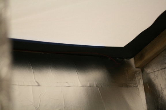
We ran through many different software packages to do blob tracking, and eventually settled on Touchlib, a C-based package from the NUI Group--NUI stands for Natural User Interface.
Touchlib integrates all of the camera capture, filter, and threshold algorithms into a neat package. It also allows for symbol recognition in case we wanted to add other objects to our system besides human fingers.
The most valuable feature of Touchlib is the support for DI. It has a number of very useful filters and thresholding algorithms that are designed specifically for DI, allowing us to quickly prototype and test different DI configurations.
We’ve used it with great success so far.
Hardware
Rev 0 (FTIR)

Our earliest prototype used both visible and IR light. We were curious to see if the FTIR effect was feasible, so we used visible light for quick testing and debugging. The best results were achieved using a piece of plexiglass, a laser pointer, and a mirror. Putting the edge of the plexiglass up to the mirror and shining the laser pointer in from the opposite edge, we were able to set up a nice TIR. Touching the plexiglass with our fingers resulted in a very clear, sharp FTIR emission.
Having validiated that FTIR works, we moved to IR light. We used a modifed webcam with IR notch filter removed, and the exposed, developed 35mm film as an IR bandpass filter. We saw minimal results with the FTIR unless in near pitch-black darkness, but we weren’t using many IR LEDs.

|
Working in Bathrooms
It turns out the darkest rooms in the building we were working in were the bathrooms. I can’t say how many other students we startled when they walked into a dark bathroom only to find several students clustered around a laptop and our prototype. |
Rev 1 (FTIR)
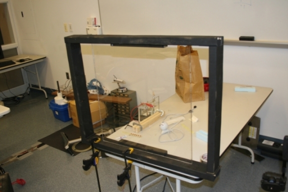
Revision 1 was short-lived. We had decided to move to a larger piece of plexiglass, both to make projection feasible and to increase the available edge area for more IR LEDs. We built a wooden frame to hold the plexiglass, and clamped it to a table.
The biggest contribution of Revision 1 was the new IR LED arrays. Using techniques learned in Olin’s freshman course Design Nature, I designed some LED holders out of Delrin that clip onto the edge of the plexiglass and maintain good spacing between LEDs for regular lighting.
The downsides of Revision 1 were primarily the lack of adequate support for the plexiglass. We were taking the plexiglass out of the frame frequently to work with it, so a permanent clamp on it was unacceptable. We used a block of wood on the back side to brace the plexiglass against our pressing on it, but there was nothing holding it in from front other than some thumbtacks.
Rev 2 (FTIR)
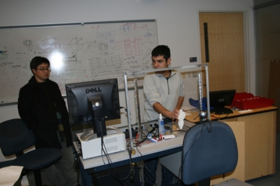
Olek, having seen the shortcomings of Revision 1, took it upon himself to build a new frame for us, using aluminum L-brackets.
Olek welded L-brackets together and used screws and washers to clamp down on the plexiglass. The screws were easily removeable, and they were more than adequate for holding the plexiglass in the frame.
We used the Delrin LED array brackets on Revision 2, sanding down the tips of the LEDs and epoxying them into place. The epoxy, we hoped, would ensure a good optical channel for the IR light to travel through. However, even though we were flooding the plexiglass with IR, the FTIR wasn’t performing adequately.
We used Revision 2 for our first demonstration to the rest of the college, but we had to do it in a dark room due to the sensitivity to ambient IR. Also, to ensure good contact between human skin and the surface of the plexiglass, we dipped our fingers in water before using the touchscreen. It also became very tiring to use the touchscreen, since it was angled vertically, which is a very awkward position for the user’s hands, especially when the user has to push very hard to get a response.

|
Getting Wet!
Dry fingers do not work very well with FTIR. It turns out we had the best results with water, but applying moisturizing cream to your hands works well as well. Unfortunately, the cream leaves a residue which can result in false positives. Plus, the screen becomes oily and unpleasant. |
Rev 3 (FTIR)
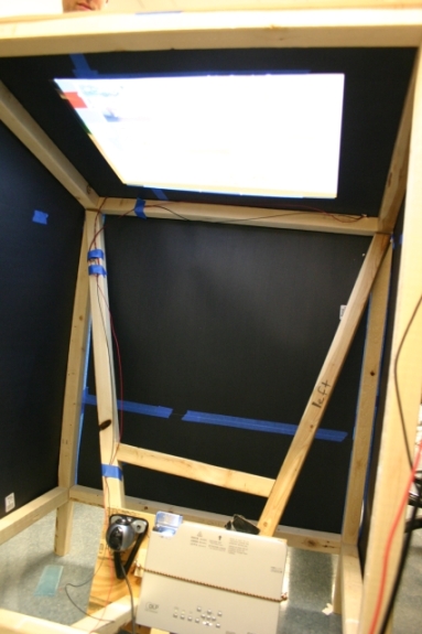
We decided we would address several issues with the Revision 3 touchscreen.
-
Ambient IR
-
LED-Plexiglass Interface
-
Touchscreen Position and Angle
-
Projector and Camera Position
The Revision 3 touchscreen is about three feet tall, contains the camera and projector mount, and has panels to cover the sides.
Ambient IR
We addressed the ambient IR concerns by covering each side of the stand with black posterboard, blocking IR. The only available route for ambient IR to enter the touchscreen is through the plexiglass itself. There wasn’t much we could do about that, but by controlling the overhead lighting we managed to mitigate any real issues.
LED-Plexiglass Interface
Sanding the surface of the the LEDs like we did in Revisions 1 and 2 didn’t work very well. We also weren’t able to polish the edge of the plexiglass to ensure good light transmission. Our solution was to bore short holes into the edge of the plexiglass, fill it with clear epoxy, and insert the LED. The epoxy cures and forms a clear path for light transmission.
Touchscreen Position and Angle
We designed the touchscreen to be used like a kiosk. The plexiglass is placed at a comfortable 3 foot height for use, and it has a slight angle to it to make it easier to see. This alleviates the issue of having to push heavily on the plexiglass because the weight of the users hands accounts for most of the required force.
Projector and Camera Position
Aligning the camera and projector was a big problem for Revision 2. Since the projector and camera were free-floating, any change in position required a recalibration. Revision 3 accounts for this by including mount points for both the camera and the projector.
Even with all the improvements, the FTIR wasn’t working well enough for us. We were anxious to get some software apps written using the multitouch interface, so I outfitted some gloves with IR LEDs in the style of Minority Report. This allowed us to develop software very quickly, using the light from the IR LEDs instead of the light generated by the FTIR effect.

|
Life’s Not Like the Movies

Figure 13. IR LED Glove
We initially configured the gloves as they are configured in Minority Report with an LED on the index finger, middle finger, and thumb. It worked for Tom Cruise, why wouldn’t it work for us? It turns out that having and LED on the thumb is very irritating. Most people are okay with folding their middle finger over to hide the LED, but they leave their thumb sticking out. This resulted in unintended input and all kinds of unintuitive and frustrating behavior. I guess movie special effects people need to get their user interface design right. |
Rev 3 (DI)
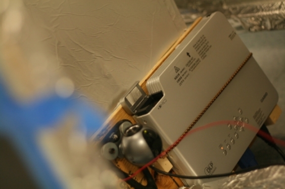
After all of these FTIR related issues, we decided to move to Diffuse Illumination (DI). We used the Revision 3 design, and simply covered the inside surfaces with aluminum foil to reflect IR light.
We initially tried using an incandescent lamp as an IR source, which worked exceptionally well as a prototype. It wasn’t diffuse enough, even with diffusing surfaces in front of it, and the camera picked up the 60Hz flicker from the mains.
We bought some IR LED spotlights, which are typically used for as illumination for IR security cams. The LED spotlights proved to be easier to control and diffuse, and we were seeing excellent results very early in the process.
Rev 4 (DI)
Finally free of the problems from FTIR, we started building a new prototype designed around DI. It is still under construction, but essentially it is a cube made of Medium Density Fibreboard (MDF) with a cutout on top for the plexiglass. The projector and camera will be contained inside the box, as in Revision 3.
Software
The multitouch interface is especially suited to applications that involve sorting and sifting through large amounts of data. It is not suited for applications that require a lot of information input.
Photo Tagging

We decided that a photo tagging application was a good fit for the interface. We can quickly sort photos by flicking them to various places on the screen with our fingers, much like we would an actual physical pile of photos.
Tagging photos is as simple as touching the tag you want, and the photos you want tagged. It’s a very simple and intuitive interface and we hope to develop it further once the hardware is up to snuff.
Lessons Learned
Software Packages
As far as Touchlib is concerned, it’s a really nice tool for getting actual data out of your setup very fast. We never bothered trying to get it to run under Linux, but we were really only interested in getting the blob coordinates.
Our very first prototype used the Java library Processing, which I believe will run under Linux. We gave that a shot at one point, but I couldn’t get the webcam drivers to integrate with it right so we gave up and settled for the Windows version. Here’s some example Processing FTIR Stuff: http://lowres.ch/ftir/
Our next software prototype used VVVV. It’s a really handy graphical language, and we were able to make more progress faster than we could with Processing. It just made changing parameters really easy because it was graphical. It also has some really nifty implementations of random media-related things, which if nothing else are amusing to look at.

|
Touchlib and Multiple Screens
I was asked by someone if Touchlib handles multiple screens. I’m not really sure if it’s limited to one screen or not. I’d imagine it is, but we never tried to get more than one running at a time. We were having enough problems getting it working in the first place. Sorry I can’t be of more help there. |
Software Infrastructure
As far as Linux vs Windows, we saw pretty heavy processor usage running any of the software packages just for one camera, so we actually broke our system into two computers. One computer ran the image processing, and the other ran the actual Multitouch app.
I’m reasonably certain that all three packages output OSC (OpenSound Control) packets if you want them to that contain blob position information, so you can actually develop your app on any platform that supports OSC that you want (I know python does, so your options are pretty broad).
I’d suggest using a Windows box for now to do the image processing. If you’re really really gung ho about it you can always use an FPGA to run the image processing and output an OSC (or whatever protocol you choose) stream. We saw ourselves going down that line in the long term, but never got a chance to finish.
We wrote a pretty simple game in Python to demo the hardware, and I can provide the source code to you if you’d like. The benefit to using something like OSC is that we kept the game unchanged, basically, and kept switching both hardware and software implementations and the game just kept on working, which was excellent for debugging.
You also could have multiple computers with cameras doing image processing and sending OSC streams to another computer that is actually running the multitouch app.
We got stuck at the end sorting out DI hardware issues—i.e. we were swamped with the whole getting out of college process, so we never got past testing the hardware with touchlib alone. I’d honestly say that touchlib was an excellent prototyping platform, and made everything easy. It does all of the filtering and image processing for you, and it even does the matrix transforms you need to calibrate the screen properly. I know it runs on Windows, but I’d honestly say that it’s worth it. I’m a huge Linux fanboy myself, so I don’t say that lightly.
Touchlib Filters

|
I was asked about which filters we used, but I’ve long since forgotten who asked… |
Well, it’s been awhile, but if I remember correctly we used a background subtract filter, a high-pass filter, and a thresholding filter. There might have been some smoothing filters in there as well, but those are the big three important ones.
That seemed to work very well for us. The biggest problem for us was achieving uniform illumination across the whole screen. We were using IR spotlights (typically used for home security camera night-vision purposes) and aluminum foil as reflectors to illuminate our screen. This really affects the thresholding algorithm, because the filter assumes that the light intensity is uniform.
